 Quick Navigation
 All projects
  Hardware
 Links
Links Top projects
Alan numitron clock
Clapclap 2313/1386
SNES Pi Webserver
USB Volume/USB toys
Smokey amp
Laser cutter
WordClock
ardReveil v3
SNES Arcade cabinet
Game boy projects
cameleon
Home Presence Detector
 GitHub
AlanFromJapan
 Contact me
 Who's Alan?
Akizukidenshi
Elec-lab
Rand Nerd Tut
EEVblog
SpritesMods
AvrFreaks
Gameboy Dev
FLOZz' blog
Switch-science
Sparkfun
Suzusho
Datasheet Lib
Reddit Elec
Ermicro
Carnet du maker (fr)
atomic clock
Last update: Tue Feb 17 20:52:01 2026
Presentation
Principle
Use a Rubidium Frequency Standard (model FE5650a Option 58) as a counter: you start at a point of time, you use the RFS to measure time passing by ans since it's ultra precise, you're in for an extra precise time keeping.Points of interrest
Schematics
In my case the wiring will be:
Bill of materials
Implementation
Serial communications
All the pictures found on the net mention a Sipex SP233ACT chip as the U404 on the silkscreen, but on my RFS the trace is unpopulated and instead a tiny-tiny 8 pin TSOP chip with "FDM" written on is here. And the serial 4 pin connector is gone, replaced by a nice molex (?) connector at the top with 15 pins. So conclusion, I have a more recent version.Checking the pinout of the original SP233ACT and my tiny chip, I can see that in fact the Serial1 is implemented, and I can wire them easily (^_^)v
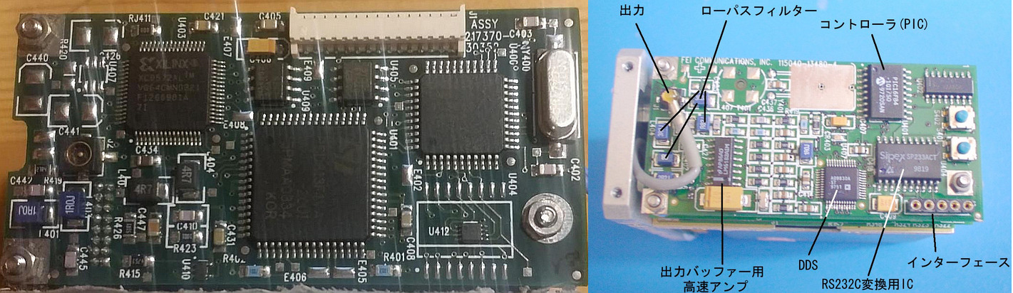
Left: what I have. Notice in the bottom-right corner the big printout free and the small chip.
Right: what I found on the net, looks pretty older compared to my version (not necessarily a good thing).
The bottom right pinout should be (left to right): Gnd - Tx - Rx - 5v - 5v
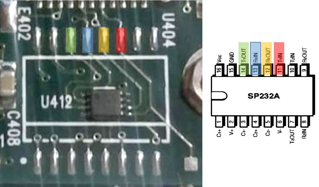
4 pins are mapped easily to the original circuit, let's use them. The rest must be power.
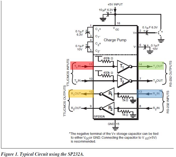
Indeed, that smells like it. We need to use the pins T1IN and R1OUT because we'll be TTL side.
Source code
Pictures
Links
Helpful sources
Inspiration
electrogeek.tokyo ~ Formerly known as Kalshagar.wikispaces.com and electrogeek.cc (AlanFromJapan [2009 - 2026])